Certifying a whole box
The hold gate answers at one pose. A certificate answers for every pose in a box of poses or disk placements, with no sampling and no Lipschitz constant.
Why
The hold gate solves a small linear program at one pose. Everything around it samples: the transition sweep tests a grid of poses, the realizer’s target χt is the best of five disk placements, and a transport checks poses along the push. A sampled test can step over a thin region where the box holds, and between its samples it proves nothing.
The certificate decides a whole box of parameters at once, here the box’s tilt θ and the disk’s offset h along the face, with finitely many linear programs and exact arithmetic where it matters.
How
- Enclose the data. Over a box, every entry of the hold program’s matrices lies in an interval. Interval arithmetic (immrax, mean-value form) computes these intervals, widened outward for rounding.
- Inside: Rohn’s theorem. The interval system has a nonnegative solution at every pose of the box if each of its 27 = 128 “vertex” systems does (Rohn; the test behind wrench-feasible workspaces of cable robots, Gouttefarde, Daney and Merlet 2011). Each vertex’s margin comes from a float32 witness whose residual is bounded rigorously, so the conclusion is exact.
- Outside: a separator. One vector, checked in rational arithmetic, proves that no pose in the box can hold.
- Split the rest, down to a declared minimum width; what is still undecided is refused, a thin band along the true boundary.
The pivot
After the pivot, breaking gv leaves the disk and the step corner, {mx, sv}, to hold the box.
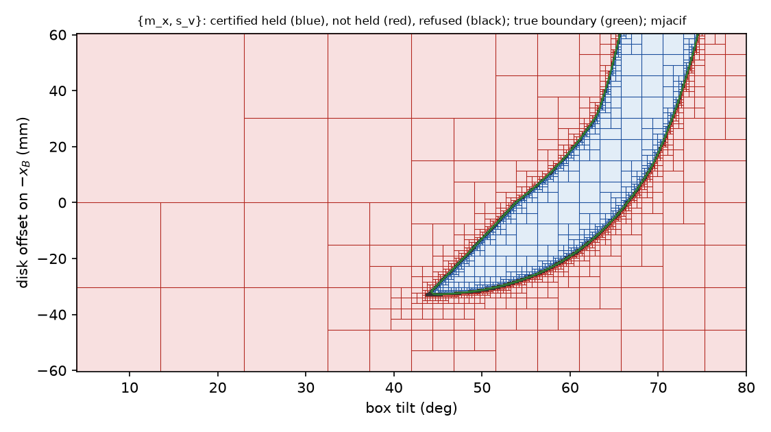
No decided box disagrees with the real gate (5 × 5 points in each, every apparent violation re-solved in float64 by HiGHS). Held tilts: 44.4° to 74.4°, as on the pivot map.
The contacts must not change inside the box
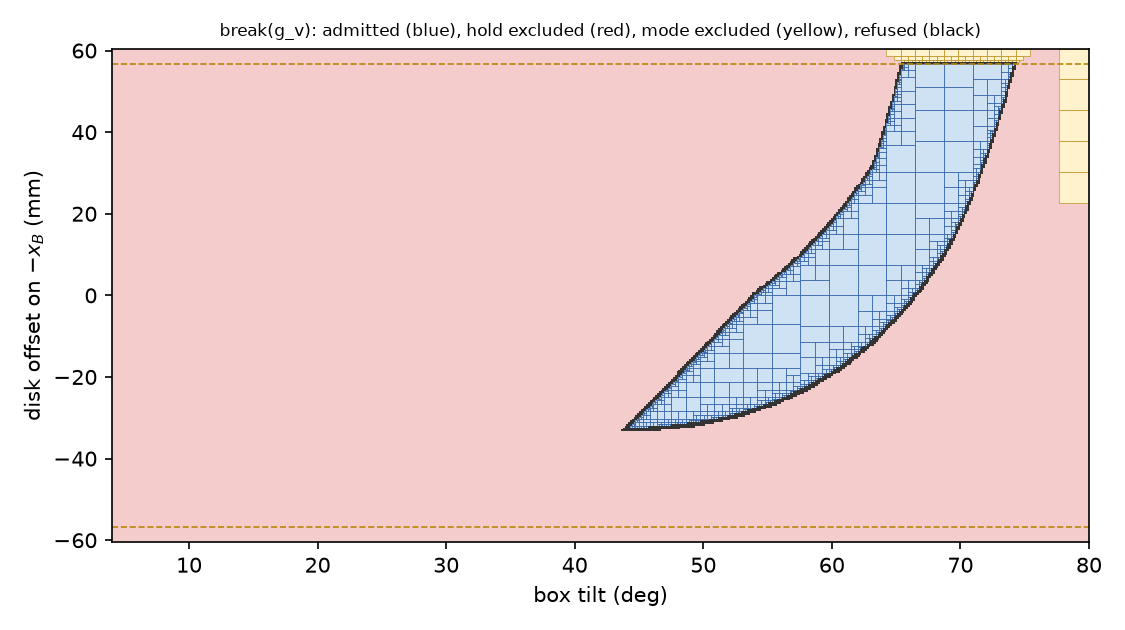
The hold program assumes a fixed set of contacts. A planner edge also needs the recognizer to read the same formation, {mx, gv, sv}, at every pose of the box, with no tie. If the step corner slides off the face, or the disk comes within a few millimeters of a box corner, the program answered a question about contacts that are not there.
The recognizer’s own rules (gaps against εon, relative interiors, the parallel test) become four interval conditions here: the tilt stays clear of the parallel angle θe, the step corner stays inside the face (θ < 75.40°), the disk stays at least 5.7 mm from the face’s corners (|h| ≤ 56.82 mm), and every other contact stays at least εon away. On 74,115 grid poses they agree with the real recognizer exactly.
Rounding. The recognizer runs in float32, so at an exact boundary it can disagree with exact arithmetic. Every threshold is moved by a bound on the float32 error: 0.6 µm for gaps, from a check of every float32 tilt (1,070,141,404 values) through the real angle computation on each machine the planner runs on, plus a rounding analysis of the rest. The bound differs by processor (the sine’s error is 9.4·10−8 on the local Ryzen and 1.32·10−7 on Ganymede2’s EPYC), so the largest is used.
What the sampled pieces miss
With the certificate as the reference:
| Piece | Against the certificate |
|---|---|
| Pointwise gate, 106 random poses | admits nothing that cannot hold; refuses 5 that can (float32 failures of one exit program) |
| Transition sweep, 2,520 starting poses | never hands over a pose that cannot hold; 21 refusals with a certified-held pose in its own reach |
| The five placements of χt | at 10–15 tilts none of the five holds while a held interval exists (44°–47°, 73°–74.5°); elsewhere a median 29% of the margin is lost |
The sampled pieces fail by refusing, never by admitting: they are safe but incomplete.
Certified placement
A branch and bound over the offset h finds a placement whose margin is certified within 10−3 of the best, with an upper bound from the interval system’s relaxation made rigorous by weak duality (an exactly checked dual). On 153 tilts it agrees with a 2,001-point search to 6.8·10−4, in about 106 boxes and 4–5 s per tilt.
| Tilt | Best h (mm) | Certified margin | Held offsets (mm) | Five placements |
|---|---|---|---|---|
| 45° | −31.3 | 0.025 | −32.8 … −29.3 | none held |
| 55° | −13.9 | 0.250 | −27.1 … +2.9 | best 0.081 |
| 60° | −1.0 | 0.368 | −19.1 … +18.3 | held |
| 70° | +42.6 | 0.593 | +17.7 … +60.5 | held |
| 74° | +60.5 | 0.138 | +54.0 … +60.5 | none held |
Sliding changes what “held” means
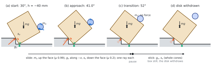
The hold test asks whether some forces inside the friction cones balance gravity. That is enough for a box at rest, but not along a motion. Under Coulomb’s law a contact that slides carries exactly one force, on the edge of its friction cone opposite the slip; only a contact that sticks may use its whole cone. On the step, the box’s floor corner and its face on the step corner must slide whenever the box tilts, and the disk, which cannot rotate, slides along the face unless it moves down at exactly the rate that cancels the slip.
So a plan is not just a path of poses: it is a stick–slip plan, a path through poses cut into segments at pauses, saying which contacts stick and which slide (and which way) on each segment. It is indexed by the path, not by time: a quasi-static motion can run a segment at any speed.
Theorem S (paper §IX, full proof in its appendix): if an edge has a certified stick–slip plan (on boxes covering the plan, the contacts stay the same, the hold is certified with the forces Coulomb’s law leaves for each segment, nothing overlaps, and the disk stays in its workspace), then a motion consistent with rigid bodies, Coulomb friction and quasi-static balance carries the edge out, from every start in a tube around the plan. Together with the earlier result that the gate never refuses a realizable edge, the certified gate accepts only edges that can be carried out.
The indirect lift
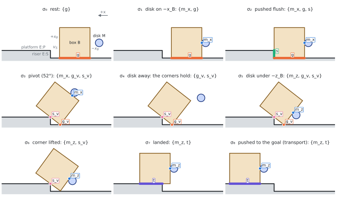
The strategy we want the planner to find on its own, from the scene alone, is the indirect lift: tip the box onto the step corner until it rests on its two corners, let the disk walk round to the box’s raised underside, then lift the corner and roll the box onto the platform. The box is held at every instant; no throw or release is needed.
Its first step, break(mx) from a 30° tilt with the disk 40 mm low, is certified end to end (the figure above); the remaining steps (the disk walking round, the lift, the roll and the final push) are being certified the same way.
What is next
- Certify the rest of the indirect lift, and wire the certified gate and placement into the search, so that the planner finds the indirect lift routinely without hints.
- Execute certified stick–slip plans in simulation: a tracker that slides the disk where the plan says slide and keeps it sticking where it says stick.
- Friction: the planner, the certificate and the simulator should use the same disk friction (or a band covering it).
The details, derivations and all runs are in the technical report, Chapter 15.