1. The planar contact layer
Critical-path step 1: which contacts are on, where they touch, and whether the box holds.
Code. Branch phase1/planar of Symplectomorphism/c-gnn: commits ca4123b (contact layer), 2114cf5 (compendium), 21727bb (paper), b2665cb (finite gradients, robustness tests), 62782b8, 5f5a2e8 (θe derived) and 583810b (known issue recorded). Python 3.14 (cmg/.venv314); Angelo’s MPPISolver, Cand and Search run on it unchanged.
What step 1 replaces
The walkthrough ended on a list of defects in the contact layer (page 9). The main one: faces are closed sets that share their edges, so one physical contact lit 3 to 6 template bits at once, on every frame of the demo. The search, the hold test and the graph all inherited that over-count. Step 1 rebuilds the layer in the x–z plane with the paper’s contact names. Exactly one contact per body pair is on, and each contact carries its contact set, the part of the box that actually touches.
The scene
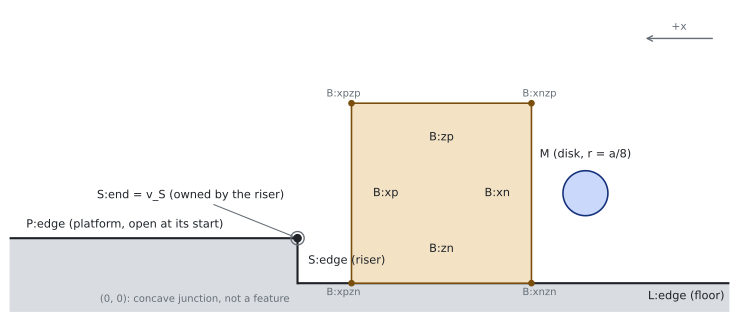
step2d.yaml declares the scene with dimension: 2. Its catalog has 40 templates: 8 disk–box, 8 box–floor, 16 box–riser and 8 box–platform. The paper’s count is 44 because it also lists the four disk–environment contacts, which the code leaves out. The seven named contacts are g (box bottom on the floor), gv (box corner on the floor), s (box side flush on the riser), sv (step corner on the box side), t (box on the platform), mx and mz (disk on a box face). The exclusions {g, t}, {gv, s}, {g, sv} and {g, mz} are given by name.
When a contact is on
For each body pair, a template is on when all of these hold:
- In band. Its gap is between −εpen and εon = 1 mm.
- It touches inside both features. The touching part may not sit only at an endpoint the feature does not own. A box edge touching the floor only at its end is the corner’s contact, not the edge’s. The step corner counts for the riser, not the platform.
- Edge on edge needs alignment. The two edges must be within θe ≈ 1.83° of parallel (derived below) and overlap by at least ℓmin = a/16 (7.8 mm). Otherwise the contact is a corner contact.
- The higher-dimensional contact wins. A corner contact inside a flush edge contact is not counted separately. Any tie the tolerances leave goes to the higher-dimensional contact.
This is the principal-contact rule of Xiao and Ji (2001) with tolerances, written in the paper as def:near-map.
The demo, frame by frame
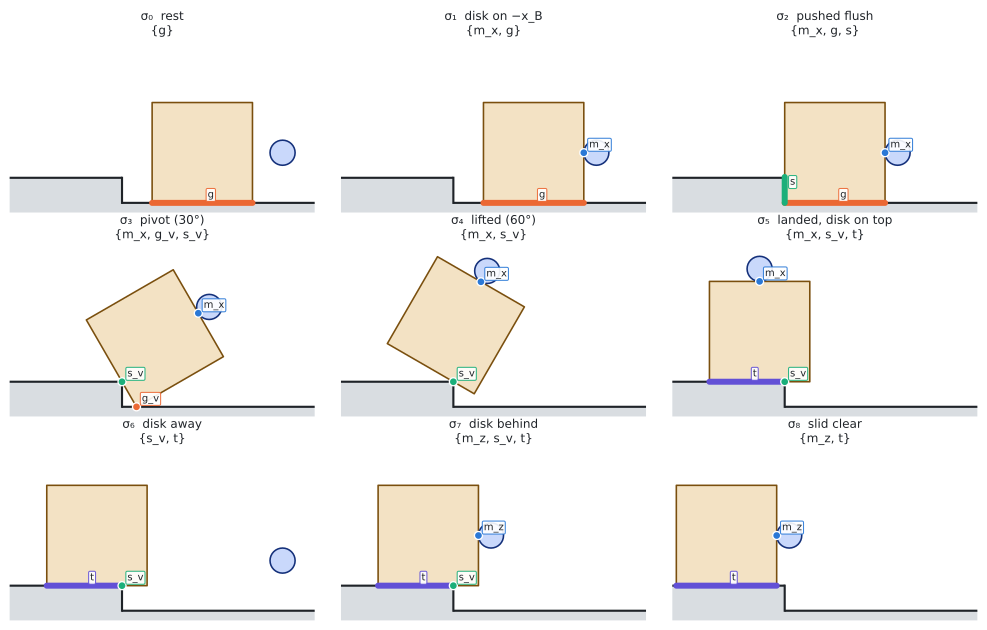
The viewer replays the 1,721-frame demo shipped with cmg (step_example_trajectory.npz). It labels every frame with the new layer and draws the contact sets.
Open the viewer on its own page for more room.
What to watch for:
- One bit per pair. The table’s “in band” column is the old closed-feature count: up to 6 for one contact. The on column never holds more than one.
- The chain, in order. The formation goes {g} → {mx, g} → {mx, g, s} → {mx, gv, sv} → {mx, sv} → {sv} → {sv, t} → {mz, sv, t} → {mz, t} → {t}. It never shows an excluded formation.
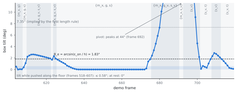
- Two rocks the chain leaves out. At frame 609 the box hits the riser and rocks onto its corner, up to 2.6°. After landing (frames 708–712) it seesaws on the step corner with its platform end up, so only sv is on. Both are real motion; the next section is about them.
- One vertex–vertex frame (920): box corner on the step corner as the disk pushes the box clear.
- Tie-breaks fire on 2 frames, both with the box pressed more than 1 mm into the riser.
Edge contacts and the tilt θe
This was the first of step 1’s refinements to review. It is settled: θe is derived from the 1 mm contact tolerance and the scene’s shortest edge, θe = arcsin(εon/h) ≈ 1.83°. Nothing is tuned to the demo.
What we had agreed. An edge counted as flat on a surface when the part of it within εon = 1 mm of the surface was at least ℓmin = 7.8 mm long. A box tipped by θ with its corner down keeps a 1 mm sliver of length εon/sin θ. So the length rule already called the box flat up to arcsin(εon/ℓmin) = 7.35°, when its far end is 16 mm off the floor.
Why the length rule failed. As the box tips over the step corner, the floor’s contact set ends at the box corner, but the riser’s runs about εon past the step corner. The floor contact turned into a corner contact at 7.35° and the riser contact only at 8.44°. In between, the label was {gv, s}: on a corner yet flush on the riser, which is impossible for a rigid box in a right-angled corner. Testing the angle instead makes both contacts switch at the same tilt, because they share the box’s angle.
What the literature does. No tradition uses an angle for “flat”:
- Exact contact-state theory has no tolerance at all (Xiao and Ji 2001).
- Recognizing contact states under sensing error either grows each feature by the pose uncertainty and reports every formation that fits (Xiao 1993), or filters over the graph of formations with a sensor-noise model (Meeussen et al. 2007).
- Physics engines test contact points by distance only, so a face contact is several point contacts, and they use separate distances to make and to break a contact (Bullet, MuJoCo).
Two principled options.
| A. Point rule: both ends of the overlap within εon | B. One derived angle: θe = arcsin(εon/h) | |
|---|---|---|
| Source of the number | εon only | εon and the shortest edge in an edge contact (the riser, h = a/4) |
| Floor and riser switch together | no: floor at 0.46°, riser at 1.83° | yes, both at 1.83° |
| Demo | 20 runs; the excluded {gv, s} on 13 frames | 17 runs; no excluded formation |
| Exclusions and Decision 7 | {gv, s} becomes a real formation, but only over a 1.4° band of tilt; Imp shrinks and the pass-through edges are no longer forced | unchanged |
| Accuracy | exact to 1 mm everywhere | exact on the riser; on the floor the far end may be up to 4 mm high |
B is adopted. Its only extra formation would be a 1.4°-wide sliver that no controller could hold, so a robust planner (Decision 6) would never use it. B merges that sliver into its neighbors, which have real margins, and keeps the exclusions and the paper’s chain. On the riser B is exactly the engines’ point rule. ℓmin now only sets the minimum overlap.
The sweep below labels the same demo at several single thresholds:
| θe | Formation runs | Rock at the riser | Seesaw after landing | Flicker | Excluded formations |
|---|---|---|---|---|---|
| 1° | 16 | yes | yes, plus a 1-frame corner contact on the platform | none | 0 |
| 1.5° | 15 | yes | yes | none | 0 |
| 1.83° (adopted, derived) | 17 | yes | yes | one (tilt hovers at θe, frames 623–625) | 0 |
| 2° | 17 | yes | yes | one (frames 622–625) | 0 |
| 2.5° | 15 | 4 frames | 2 frames | none | 0 |
| 3° to 7.35° | 11 | no | no | none | 0 |
The flicker shows up under every single threshold that sees the rocks, including the point rule, so it can’t be what picks θe. The solver’s own rollouts show the same rock: pushing the box into the riser tips it 2.5° on impact. The solver itself only reads gaps, and gaps do not depend on θe.
Deferred: hysteresis for trajectory labels. When a trajectory is labeled frame by frame (an execution monitor, the replay, data for the ranker), two thresholds, one to make a contact and one to break it, remove the flicker. Hysteresis, not a minimum dwell, is the standard cure for chattering (Hespanha, Liberzon and Morse 2003). A 3-frame dwell was tried and rejected because it also swallows real one- and two-frame formations, such as the vertex–vertex frame 920. The two thresholds should come from a noise model, as in the filtering literature, and the simulator has none. So this waits for the execution monitor and the robot’s perception noise. The on-set N(χ) itself stays a function of the pose alone, because the search and the solver query single poses.
The other two refinements
- Penetration is charged to the nearest surface (approved). A penetration counts against the nearest environment segment or segment endpoint. Without this, a box face 2 mm into the riser read +1.6 mm (s off, sv on), and a box corner 1.6 mm past the riser read −31 mm into the platform. The computation is exact: along a box edge every condition is linear, or a convex quadratic near an endpoint.
- A counted tie-break (kept as a fallback, with a known issue). When tolerances leave two templates of one pair, the higher-dimensional one wins, then the smaller gap, and every use is counted (
tie_breaks). On the demo it fires on 2 of 1,721 frames (608–609): s and sv both survive with the box 1.1–1.8 mm into the riser, and s is chosen.
On 4,000 demo poses jittered by about 3 mm and 1.7°, 357 have a tie (median penetration 5.3 mm). Mostly, both corners of one box edge count as touching while the edge is tilted past θe (the box has sunk into the platform or the floor), or the disk presses deep near a box corner. The cause is the lopsided contact band: a contact counts as touching from 10 mm inside (εpen) to 1 mm outside (εon), so both ends of a tilted edge can be “touching”, which exact geometry never allows. The demo’s own contacts penetrate at most 1.9 mm (95% under 0.7 mm).
Step 2 will (i) set εpen from penetration measured in the solver’s rollouts (the demo suggests 2–3 mm), (ii) treat a tie as ambiguity, as Xiao (1993) reports it: a tied pose cannot become a search node or count as a solver success, and (iii) add the jittered-pose stress test to the suite. Widening the containment test by the penetration depth was tried and rejected: it removes the 2 demo ties but only 13% of the stress-test ties.
The hold test on contact sets
physics/hold.py now supports each contact at both ends of its contact set instead of one tie-broken point blended by smoothing. On the named poses:
| Pose and asserted formation | Holds? |
|---|---|
| Box flat, {g} | yes, with a real margin |
| Box flat, nothing asserted | no |
| Tipped 30°, disk pushing, {mx, gv, sv} | yes |
| Same pose, disk let go: {gv, sv} | no (break mx refused mid-topple) |
| Tipped 60°, {gv, sv} | yes (center of mass past the corner) |
| Landed, {sv, t} and {t} | yes |
| Landed but overhanging (center of mass at x = −0.02), {sv, t} | no |
A support-interval oracle (the exact range of support a contact set can give) agrees with the LP.
Tests, speed and reproducibility
- Tests.
tests/test_planar_contact.pyhas 21 tests, 25 items with the parametrized cases. They cover the schema and its rejections, the kernels against sampling references, finite gradients, the chain, the named poses, Decision 4’s table, the switch at θe, corner ownership, the disk rounding a corner, the demo sequence above, hold acceptance and the oracle. The full suite (31 items) passes on Python 3.14 (CPU and GPU) and on Python 3.12. - Speed. The planar gap takes 22 ms per 7,680 configurations, against 57 ms for the 3D catalog. One full MPPI call takes 10 s on the RTX 5080 against 36 s on the CPU.
- Reproducibility. CPU runs repeat exactly. By default GPU runs repeat inside one process but not between processes, because XLA picks its kernels at compile time: the same MPPI call ended once with the box flush and once tipped 1.4°. With
XLA_FLAGS=--xla_gpu_deterministic_ops=true, three separate processes gave identical results, at about 13% more time per call. CPU and GPU never agree bit for bit, so compare success rates across them.
Still open
The full list, across the code and the paper, is on Known issues.
- Ties under deep penetration (the known issue above): step 2.
- Hysteresis for trajectory labels, once the execution monitor and a noise model exist.
Candproposed a second contact for a pair that already had one; step 2 added the Valid check (page 2).- Paper backlog: the chain’s renumbering, the labels of Figure 1 and the theory items still follow the old chain (status board of the compendium).
Reproduce
cd ~/repos/research/c-gnn && git switch phase1/planar && cd cmg
uv venv --python 3.14 .venv314 && source .venv314/bin/activate
uv pip install -e ".[dev,cuda]" matplotlib     # drop ",cuda" without an NVIDIA GPU
JAX_PLATFORMS=cpu python -m pytest -q tests/test_planar_contact.py
# the figures and the viewer data on this page:
JAX_PLATFORMS=cpu python <website>/research/nonprehensile/planar-build/scripts/01_contact_layer.py <out dir>
2. Valid, transfers and a certified hold gate → · Back to the planar build