System Architecture
Systems Architecture · Chapter 6
Figure 6.1 · Architecture as Combination
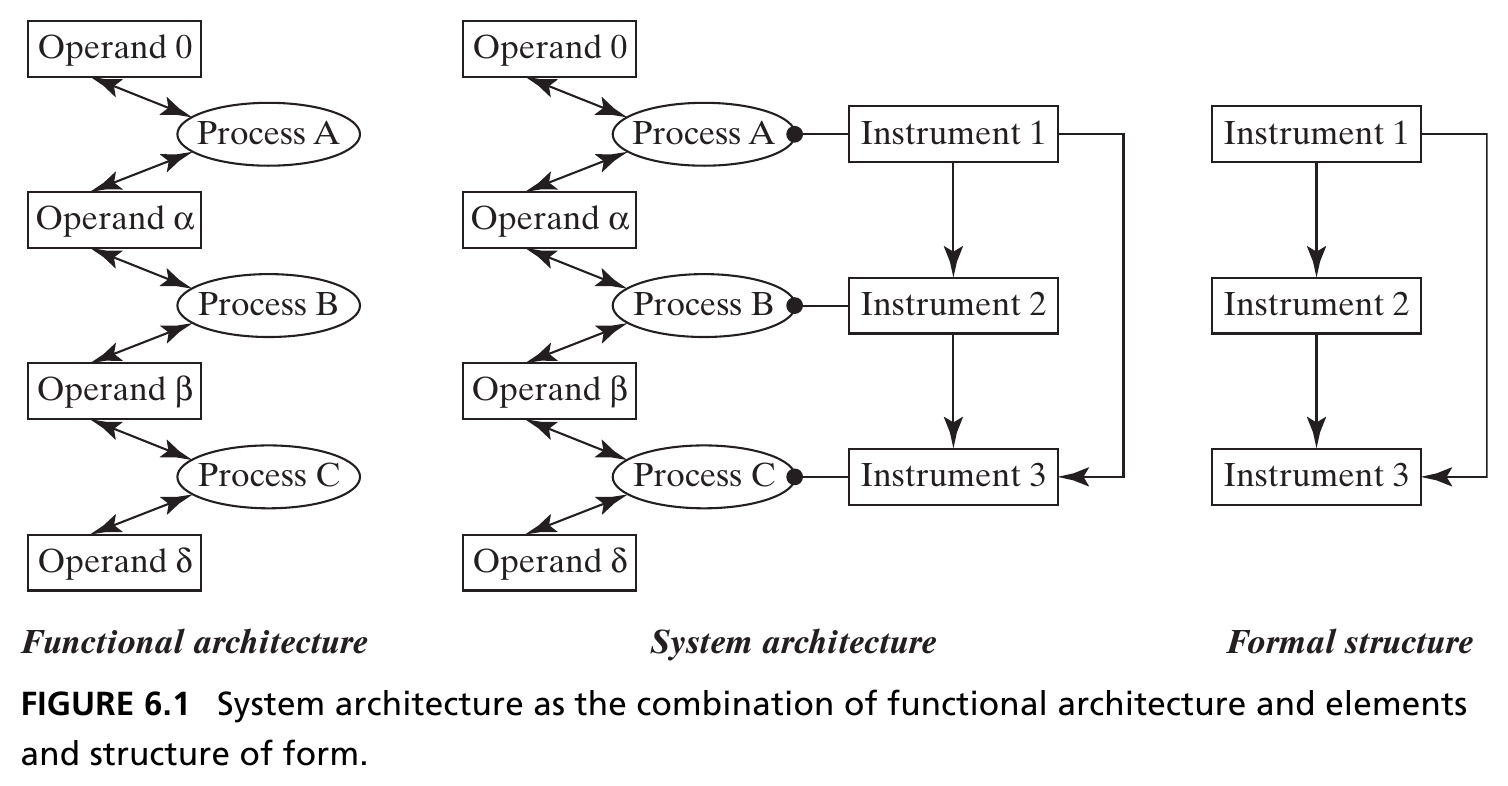
Functional architecture (left) + formal structure (right) combine into system architecture (center): each process is now linked to the instrument object that executes it. Source: Crawley, Cameron & Selva (2016), Fig. 6.1.
Figure 6.2 · Two Bridges, Two Architectures
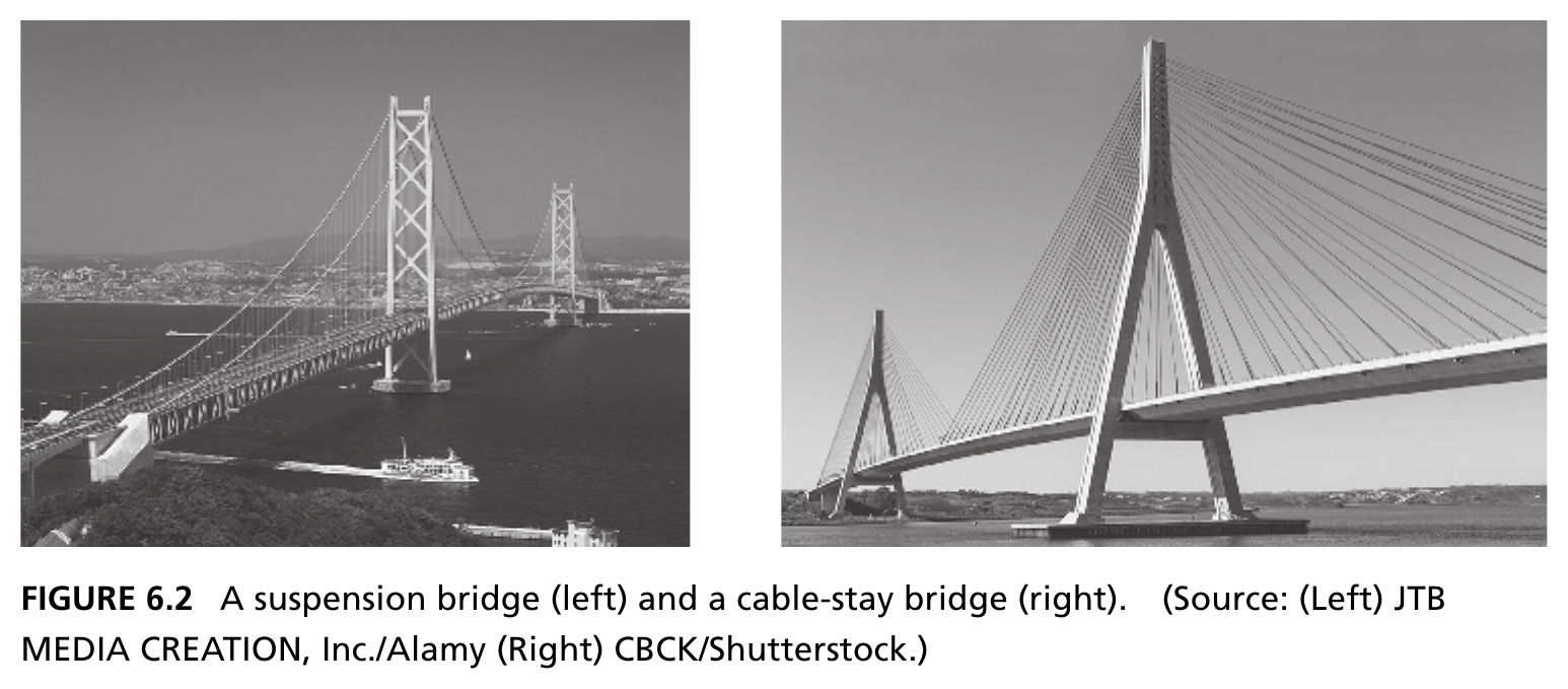
A suspension bridge (left) and a cable-stay bridge (right): same function, similar form, different architecture. Source: Crawley, Cameron & Selva (2016), Fig. 6.2. Photos: (left) JTB Media Creation/Alamy, (right) CBCK/Shutterstock.
The Simplest Case: One-to-One Flow-Through
- The center diagram of Figure 6.1 is the simplest, most commonly assumed architecture: one instrument per process, one process per instrument
- Each process produces a distinct operand: function reduces to “produce + outgoing operand”
- This illustrates the independence axiom [Suh, 1998], in which functional requirements can be satisfied independently
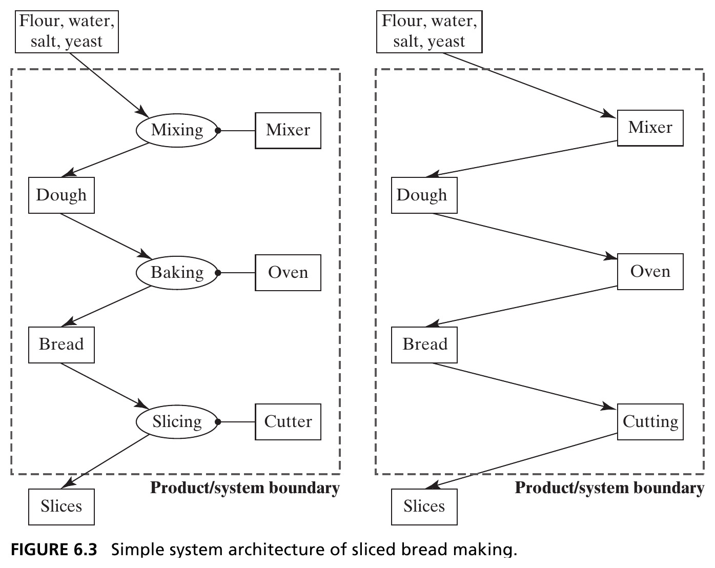
Figure 6.4 · A Not-So-Simple Architecture
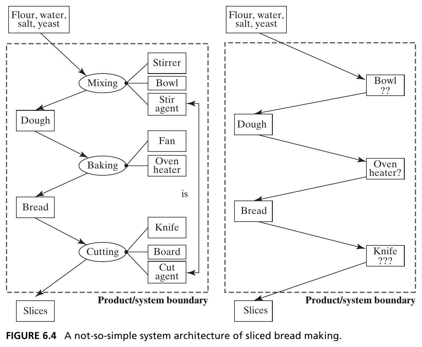
“Mixer” replaced by stirrer + bowl + stir agent (the cook): one instrument (the cook) now maps to two processes. The proxy shortcut on the right breaks down: what does it mean to go “into” a bowl or a knife? Source: Crawley, Cameron & Selva (2016), Fig. 6.4.
Figure 6.5 · Fragments of Simple Architectures
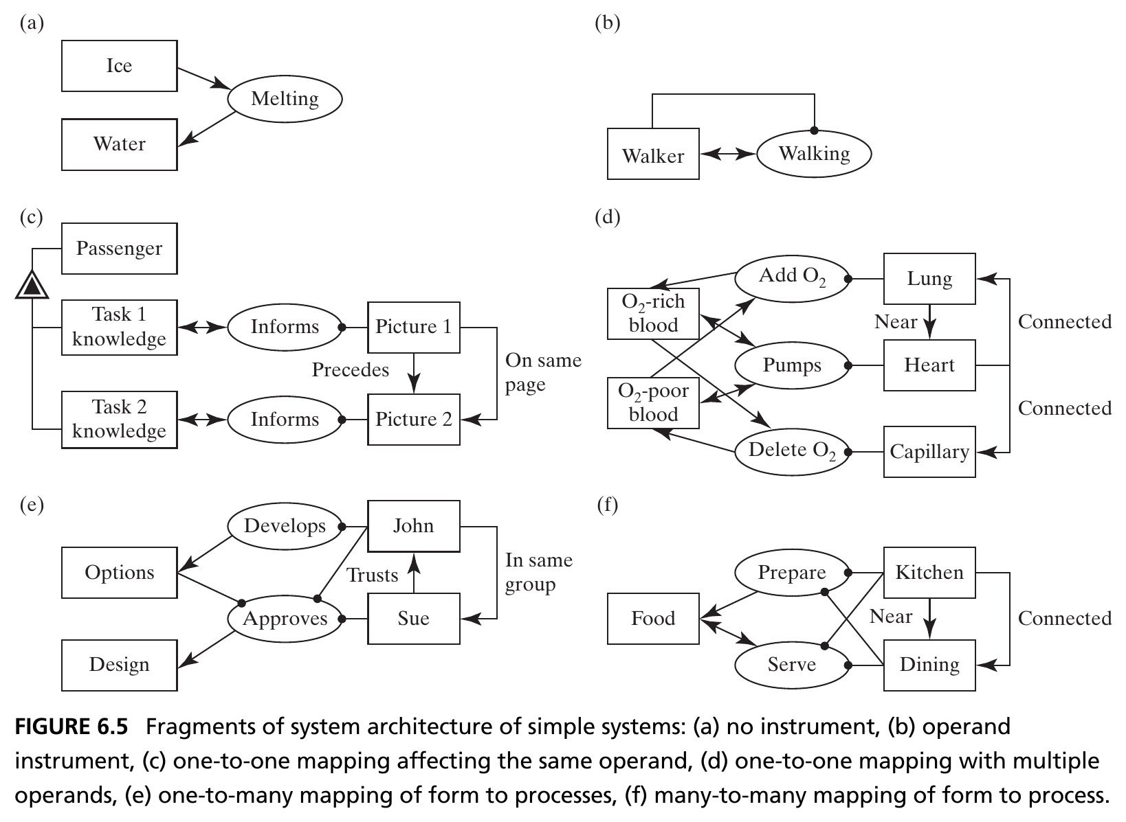
Left to right, top to bottom: (a) no instrument, (b) operand-as-instrument, (c) one-to-one affecting the same operand (emergency card), (d) one-to-one with multiple operands (circulatory system), (e) one-to-many form-to-process (Team X’s John), (f) many-to-many (kitchen/dining). Source: Crawley, Cameron & Selva (2016), Fig. 6.5.
Figure 6.8 · The Pump’s Idealized Architecture
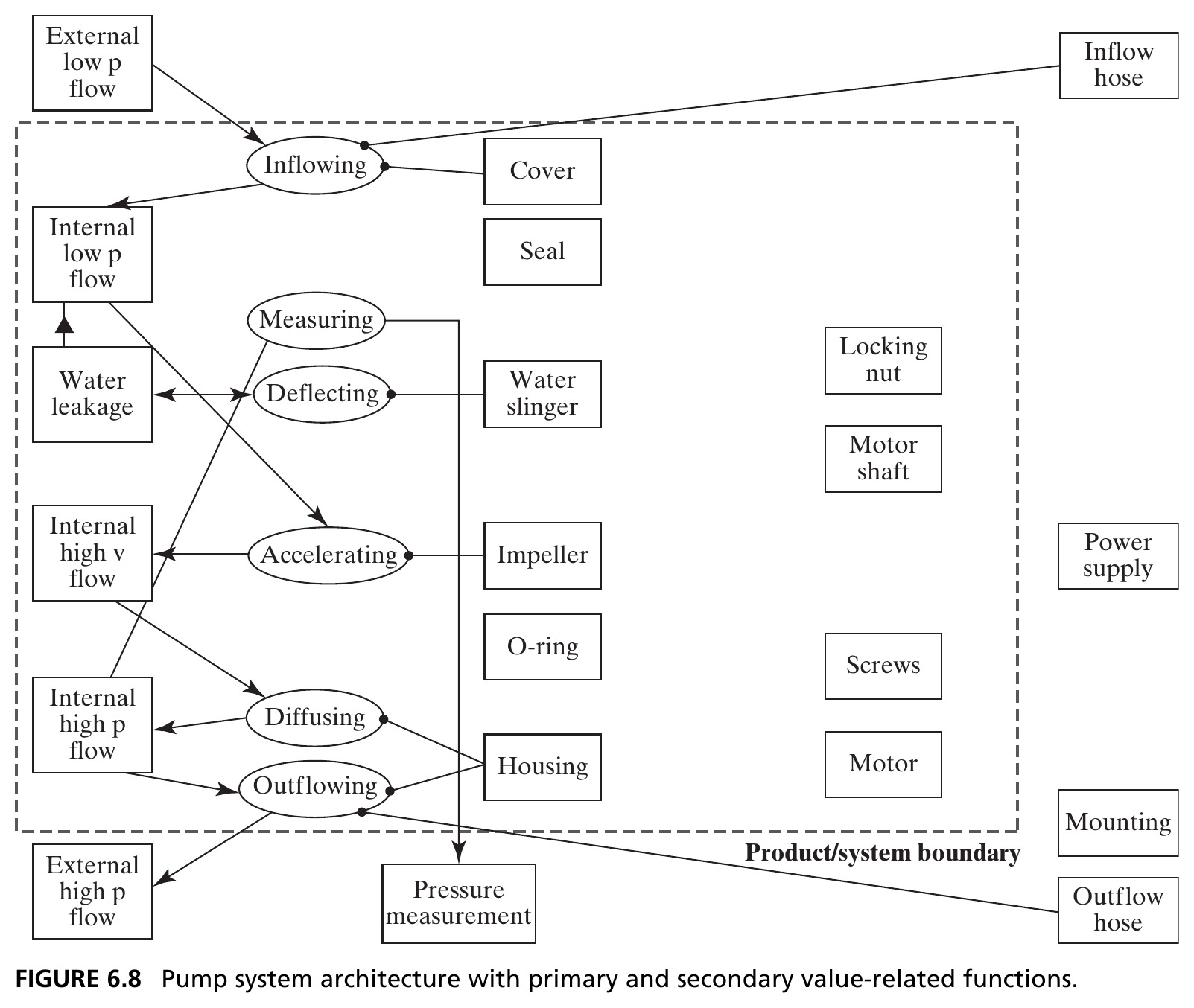
Cover, impeller, and housing map (nearly) one-to-one onto inflowing/accelerating/diffusing/outflowing, the primary value pathway, plus the secondary functions of measuring and deflecting. Many instruments (seal, O-ring, motor, screws…) are still unassigned. Source: Crawley, Cameron & Selva (2016), Fig. 6.8.
Figure 6.9 · Bubblesort’s Architecture
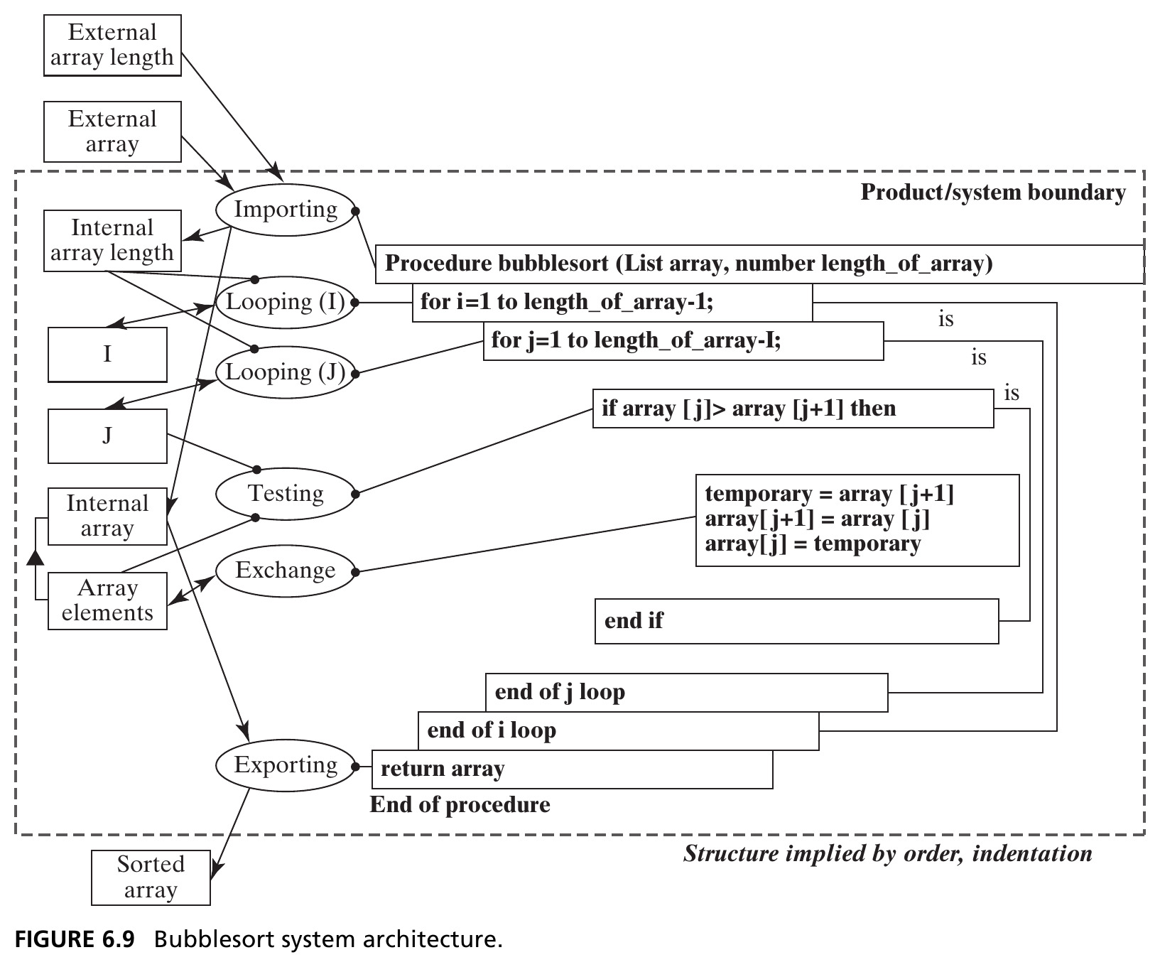
Importing, looping, testing, and exporting each map to a single line of code; the exchanging process spans three lines. The emergence of sorting is clear: the if creates conditional exchange, the two for loops add the sweep that produces the sorted result. Source: Crawley, Cameron & Selva (2016), Fig. 6.9.
Figure 6.10 · The Pump, Fully Layered
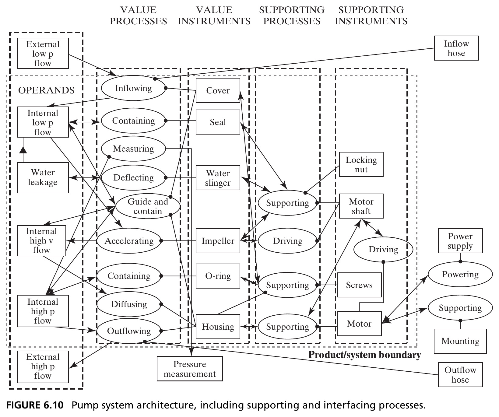
Value processes/instruments (left) plus supporting processes/instruments (right): the motor drives the shaft but also supports it; the housing (a value instrument) also supports the cover and O-ring. Assignment to a column is not unique: but instruments should sit as close to the value pathway as possible. Source: Crawley, Cameron & Selva (2016), Fig. 6.10.
Figure 6.11 · Model of an Interface
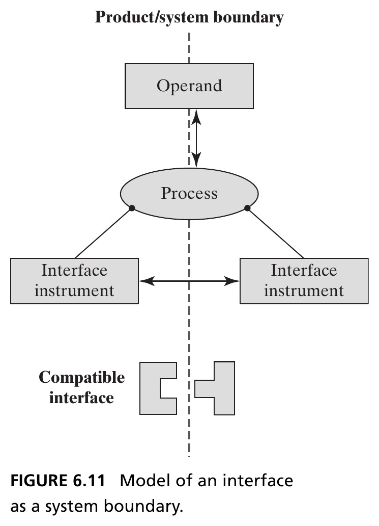
An interface has both form and function: the shared operand, the shared process, and two interface instruments: either androgynous (identical on both sides) or compatible (different, but fitting together). Source: Crawley, Cameron & Selva (2016), Fig. 6.11.
Figure 6.12 · Four Interfaces of the Pump
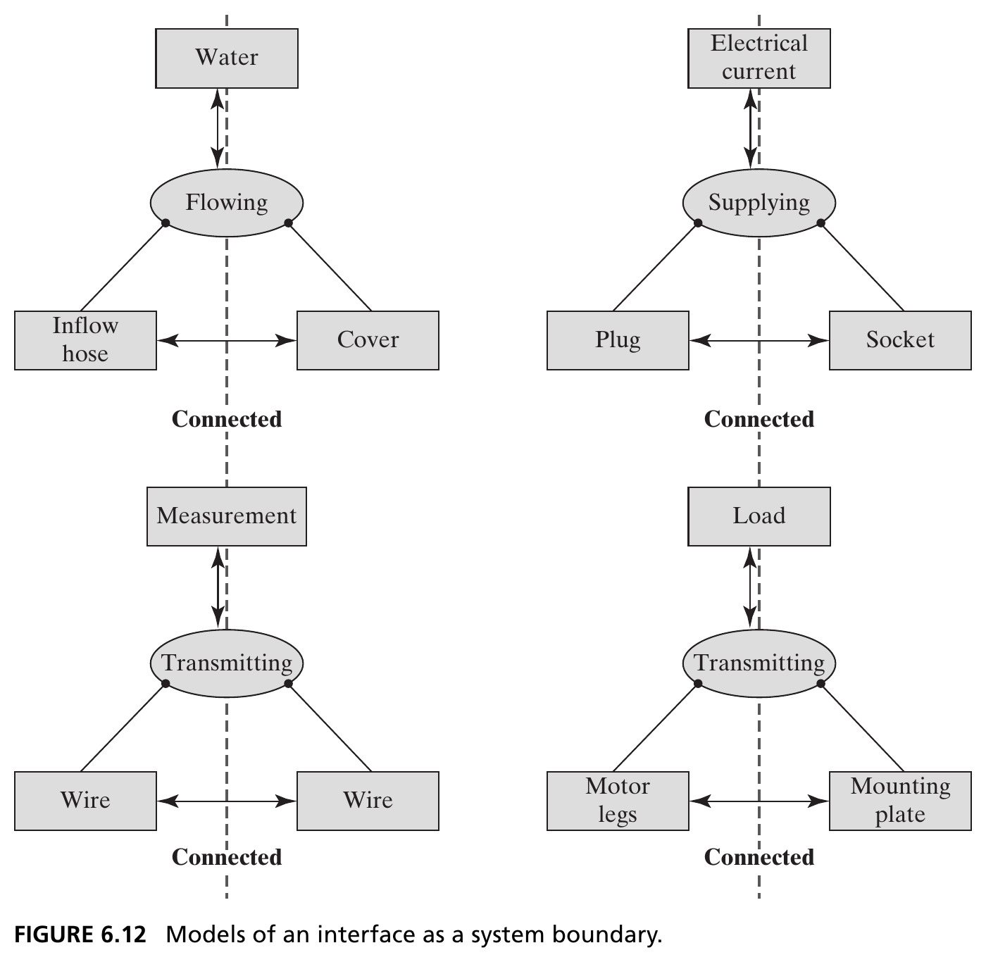
Flowing (hose ↔︎ cover), supplying (plug ↔︎ socket), transmitting-measurement (wire ↔︎ wire), transmitting-load (motor legs ↔︎ mounting plate): each pair of interface instruments is connected. Source: Crawley, Cameron & Selva (2016), Fig. 6.12.
Figure 6.13 · The Butterfly Corkscrew
- The two-levered (“butterfly”) corkscrew requires several operator actions
- The operator is essential: places the device on the bottle, twists the handle, pushes down the levers, removes the cork
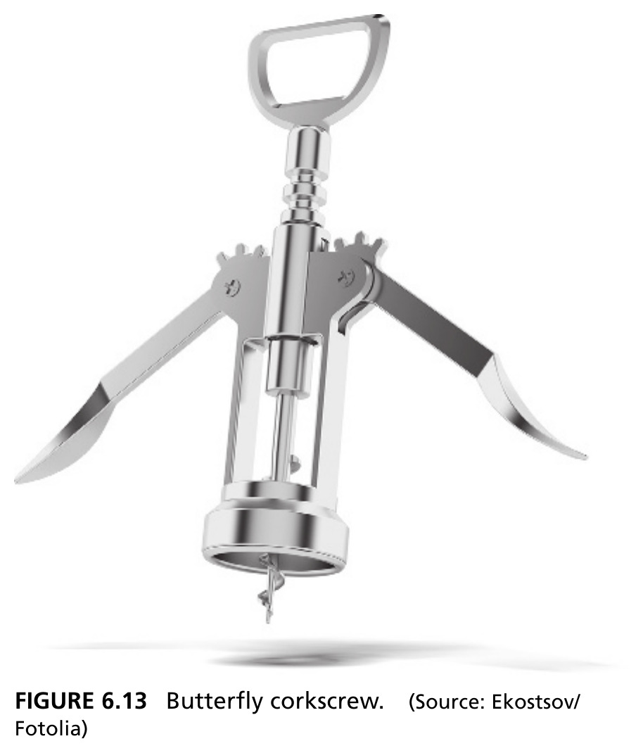
Figure 6.14 · Operations Sequence
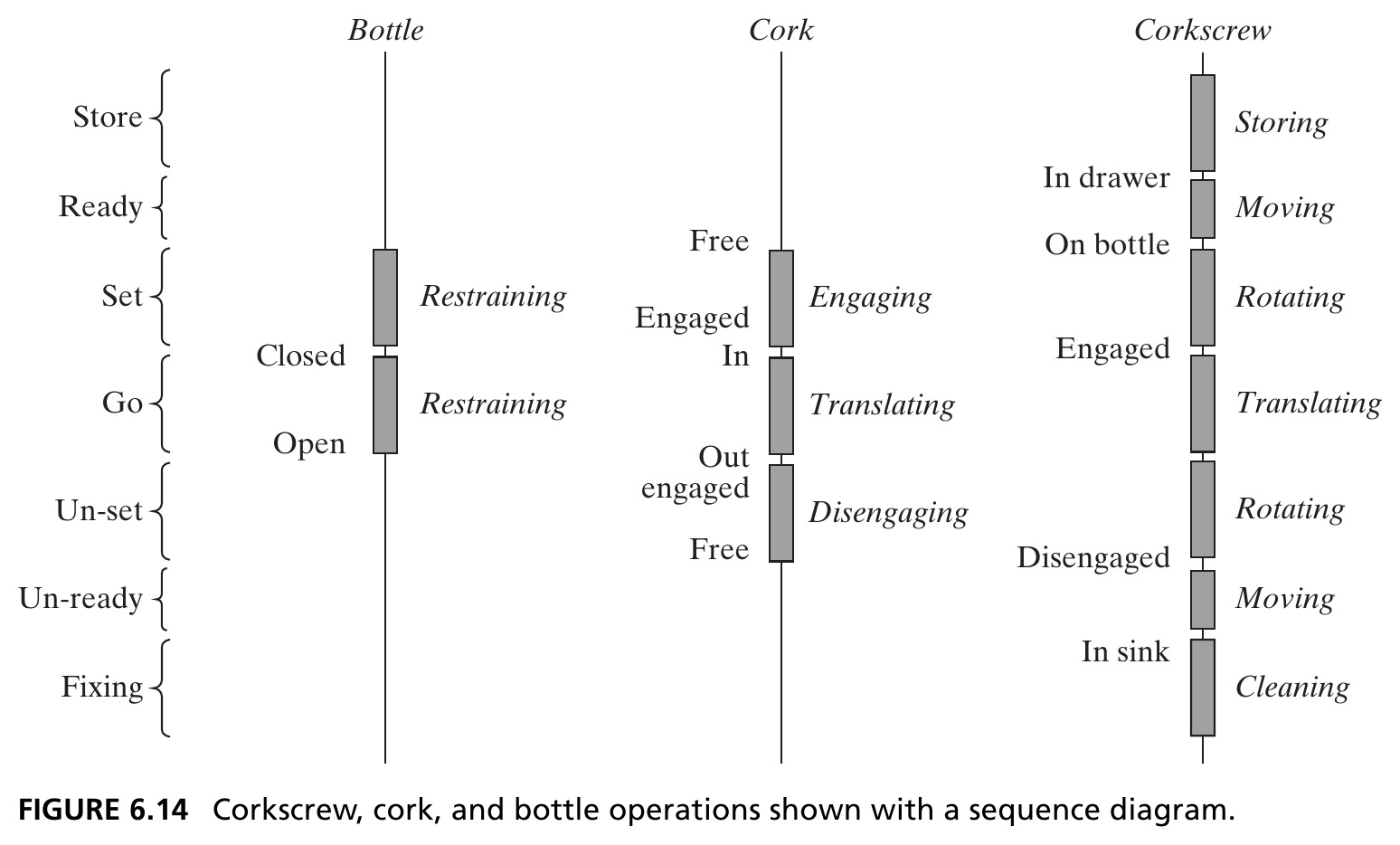
Source: Crawley, Cameron & Selva (2016), p. 141, Fig. 6.14. States appear to the left of each line; processes appear to the right.
Corkscrew Operations · An OPM View
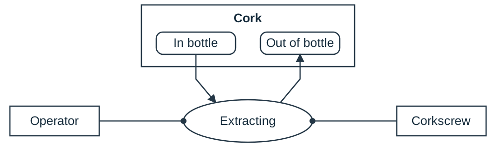
- Operand: cork; state change: in bottle → out of bottle.
- Process: Extracting; instruments: operator and corkscrew.
- Before extraction, the screw must engage the cork and the bottle must be restrained.
Course OPM adaptation of the operational example on pp. 140–142. Pointed arrows show the state change; round-ended links identify enabling instruments.
Figure 6.15 · Simplified Pump Architecture
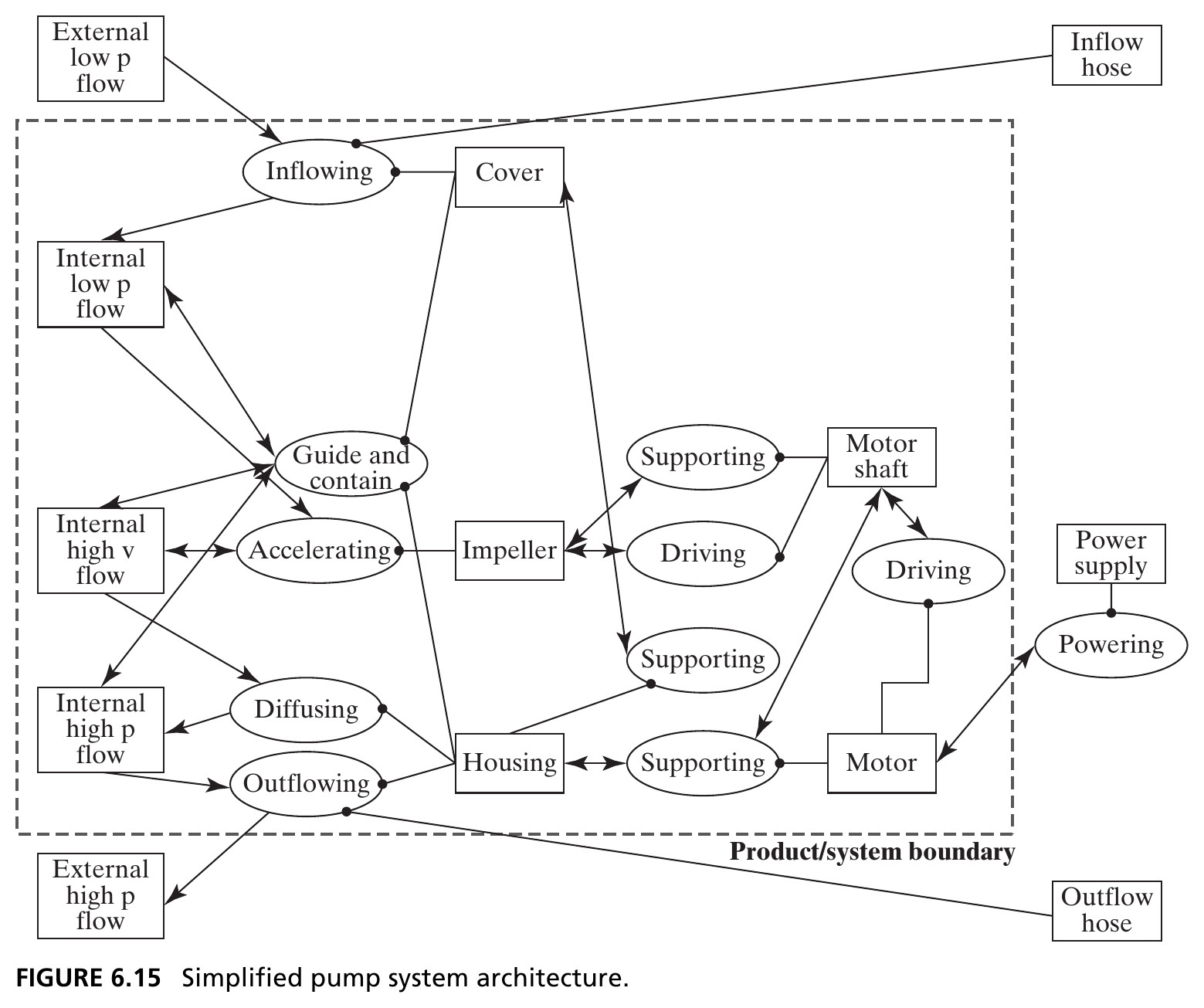
Compare with Figure 6.10: the value pathway is fully preserved; the motor shaft’s dual role (supporting and driving the impeller) stands out more clearly. Source: Crawley, Cameron & Selva (2016), Fig. 6.15.
Figure 6.16 · Projection onto Objects (Bread)
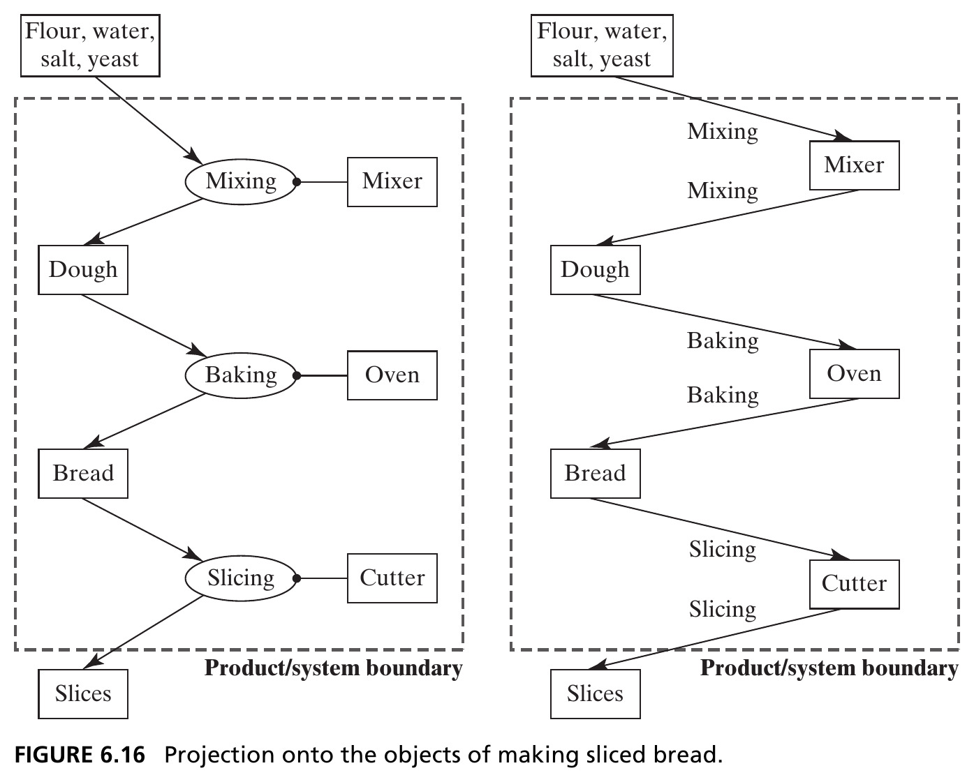
Left: the full OPM view. Right: projected onto objects: flour/dough/bread/slices connect directly to mixer/oven/cutter, labeled by the process that links them. Source: Crawley, Cameron & Selva (2016), Fig. 6.16.
Figure 6.17 · Constructing an Object Projection
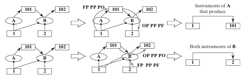
- Isolate an object: an operand or an instrument.
- Follow its link to a process, then to another connected object.
- Replace that path with an object-to-object link labeled by the process and relationship.
Keep the full model available: the new link compresses information rather than removing its meaning.
Source: Figure 6.17. Letters A/B denote processes; numbered rectangles denote objects.
Figure 6.18 · Pump Value Stream, Projected onto Objects
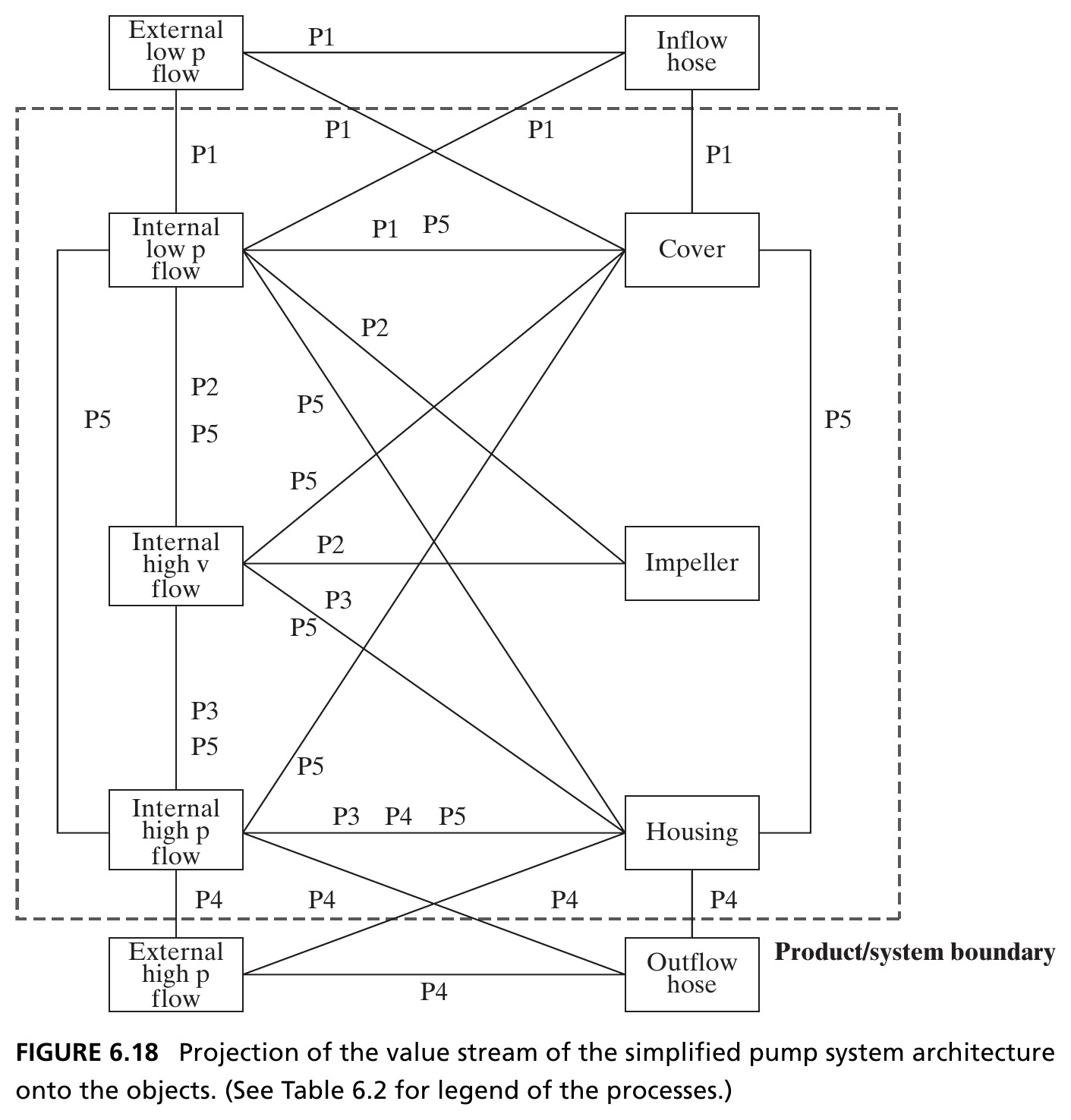
Every operand-instrument pair from Table 6.2’s value-related rows (P1–P5), redrawn as a direct link labeled by the connecting process. Source: Crawley, Cameron & Selva (2016), Fig. 6.18.
Figure 6.19 · Projection onto Form (Bread)
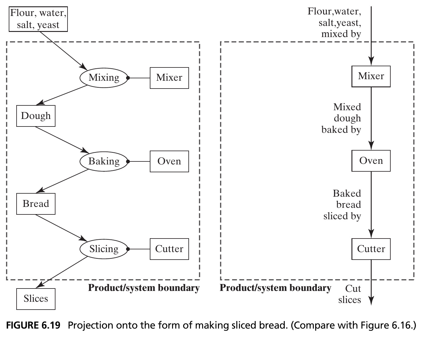
Compare with Figure 6.16: now mixer → oven → cutter are linked directly, each arrow labeled with what flows and what happens (“mixed dough, baked by…”). Source: Crawley, Cameron & Selva (2016), Fig. 6.19.
Figure 6.20 · Two Ways to Project onto Form
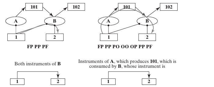
- Shared process: FP × PP × PF.
- Through an operand: FP × PP × PO × OO × OP × PP × PF.
The second path explains a handoff; the first can identify instruments that jointly enable an activity. Neither alone asserts mechanical connectivity.
Source: Figure 6.20. The two contributions can be combined in a form-to-form DSM.
Figure 6.21 · Pump Value Stream, Projected onto Form
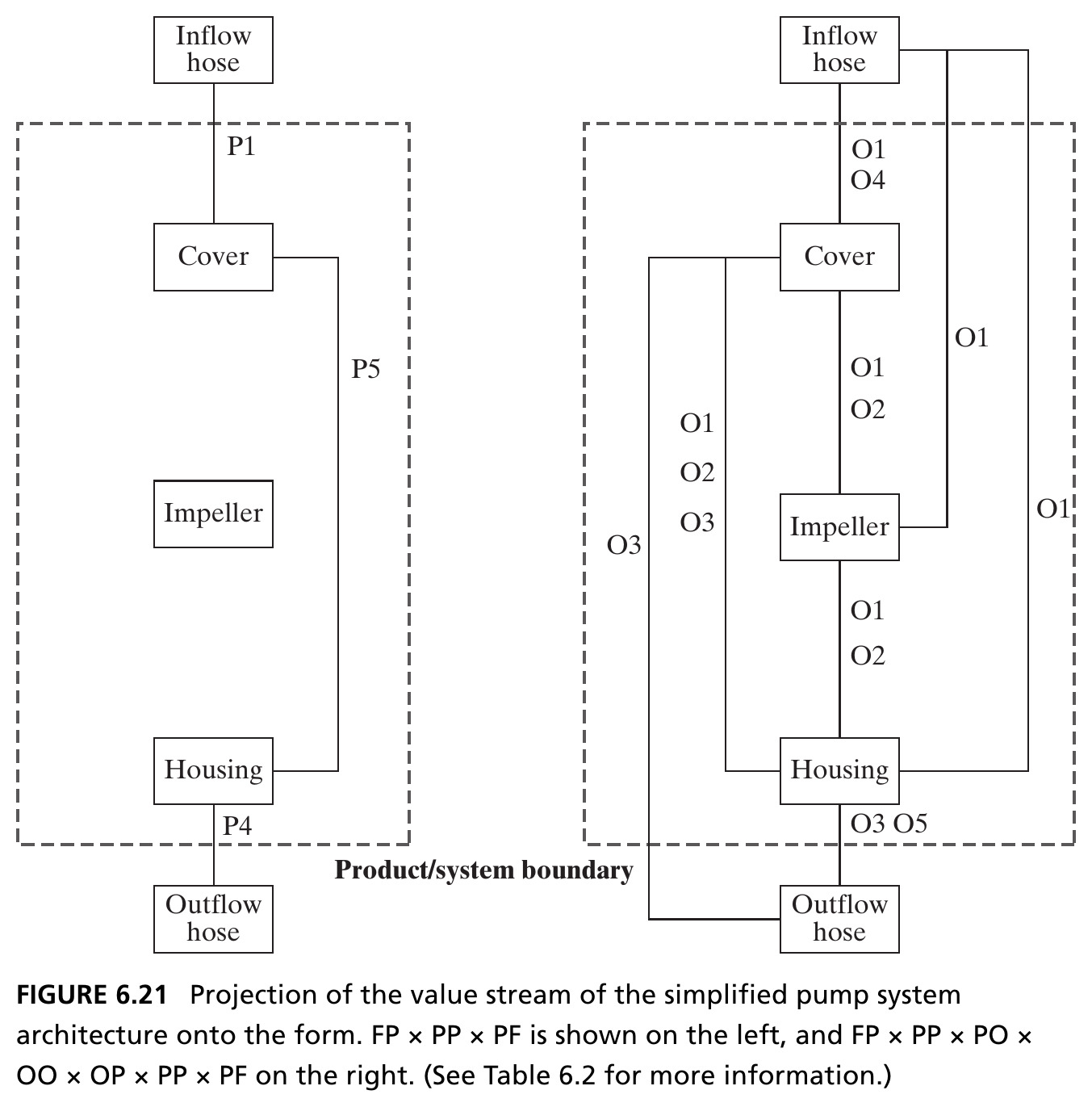
Left: form-to-form links only (FP × PP × PF). Right: the fuller projection that also threads through the operands (FP × PP × PO × OO × OP × PP × PF): the same N-squared DSM structure from Table 6.3, applied to this example. Source: Crawley, Cameron & Selva (2016), Fig. 6.21.
