Introduction
Kinematics and Machine Dynamics · Chapter 1
Chapter overview
- Machines and mechanisms
- Kinematics, dynamics, and statics
- Analysis and synthesis
- Links, joints, and kinematic chains
- Planar and spatial motion
Machines and mechanisms
A machine combines interconnected parts with definite motions to perform useful work.
A mechanism is an arrangement of rigid bodies whose connections constrain their relative motion: moving one member causes others to move.
Example: A motor-driven windshield-wiper assembly is a machine. Its linkage transmits motion from the motor to the wiper arms.
A four-bar mechanism
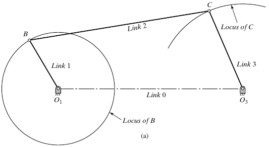
Compiled notes, Fig. 3.1. Link 0 joins the fixed pivots.
- Link 1 rotates about O1.
- Link 2 connects the moving joints B and C.
- Link 3 oscillates about O3.
- The connections transmit motion through the assembly.
Kinematics
Kinematics describes motion without considering the forces that produce it.
For a specified mechanism and input motion, determine:
- The positions and orientations of its links.
- Their velocities and accelerations.
- The paths traced by selected points.
Wiper example: Determine blade angle and angular speed from the motor’s rotation.
Dynamics and statics
Dynamics relates motion to the forces and torques acting on a mechanism.
Statics studies forces and torques in stationary systems.
| Wiper operating condition | Analysis |
|---|---|
| Moving blade, with inertia and resistance | Dynamics: find the required motor torque |
| Blade held at rest under an applied load | Statics: find holding torque and support reactions |
Analysis and synthesis
Analysis: Specify a candidate mechanism, then determine its behavior and check whether it meets the requirements.
Synthesis: Choose a mechanism and its dimensions to satisfy prescribed requirements.
| Given | Task | Process |
|---|---|---|
| Link lengths and motor motion | Calculate the wiper’s sweep | Analysis |
| Required sweep and packaging space | Choose the linkage and link lengths | Synthesis |
Links and the fixed frame
A link is a rigid body or member in a kinematic chain.
- A link may be a single part or several parts fastened rigidly together.
- The rigid-body idealization neglects deformation within the link.
- The ground link is the fixed member used as the reference for motion.
In the four-bar example, links 1–3 move; link 0 is the fixed frame connecting the two supports.
Joints
A joint, also called a pair, connects links while permitting constrained relative motion.
| Ideal joint | Relative motion permitted | Example |
|---|---|---|
| Revolute | Rotation about one common axis | Pin or hinge |
| Prismatic | Translation along one common axis | Guided slider |
The joint model describes permitted motion; it does not specify the actuator that drives it.
Kinematic chains
A kinematic chain is an assembly of links connected by joints.
- An open chain has a branch that does not close back on itself.
- A closed chain contains a loop of connected links.
- A mechanism may contain both open branches and closed loops.
For the simple closed-loop chains considered here, every link connects to at least two other links.
Example: an open-chain arm
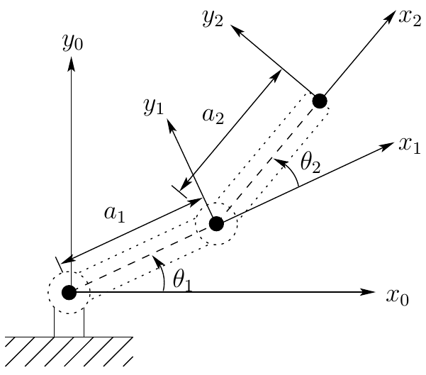
Compiled notes, Fig. 6.1. Coordinate frames will be used in later chapters.
Links: the fixed base and two moving members.
Joints: shoulder and elbow revolute joints.
Topology: the free tip is not connected back to the base. The chain is open.
Example: the closed four-bar chain
Follow the connections around the loop:
Ground → link 1 → link 2 → link 3 → ground
- The fixed frame closes the chain between the two grounded pivots.
- The moving links cannot be positioned independently.
- Every configuration must satisfy the geometry of the entire loop.
Planar motion
A linkage has planar motion when all its points move in parallel planes.
- Translation takes place parallel to one reference plane.
- Rotation takes place about axes perpendicular to that plane.
- The physical links can have thickness and occupy offset parallel planes.
The illustrated four-bar and two-link arm are planar mechanisms.
Spatial motion
A linkage has spatial motion when its motion cannot be confined to parallel planes.
Example: A robot arm with a rotating base and a shoulder joint about a horizontal axis generally moves through three-dimensional space.
The model must describe both position and orientation in space. A single planar drawing is no longer sufficient to represent its general motion.
Describing a mechanism
- Identify the useful task and the machine that performs it.
- Select rigid links and a fixed reference frame.
- Identify the joints and their permitted motions.
- Identify open branches and closed loops.
- Decide whether the motion is planar or spatial.
- State whether the task requires synthesis, kinematic analysis, static analysis, or dynamic analysis.
References and next chapter
Reading: Aykut C. Satici, Kinematics and Machine Dynamics, Fall 2020 compiled notes, Chapter 1, §1.1, pp. 3–4.
Chapter source: Charles E. Wilson and J. Peter Sadler, Kinematics and Dynamics of Machinery, Pearson New International Edition, 2013.
Next: Degrees of Freedom (Mobility) — quantifying how many independent coordinates are needed to describe a mechanism’s configuration.

← Course Home · Kinematics and Machine Dynamics · Chapter 1